

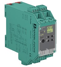
Frequency Converter with Direction and Synchronization Monitor KFU8-UFT-2.D.FA
- 2-channel signal conditioner
- Universal usage at different power supplies
- Dry contact or NAMUR inputs
- Input frequency 1 mHz ... 1 kHz
- Current output 0/4 mA ... 20 mA
- Relay contact and transistor output
- Start-up override
- Configurable by PACTware or keypad
- Line fault detection (LFD)

Please note: All product-related documents, such as certificates, declarations of conformity, etc., which were issued prior to the conversion under the name Pepperl+Fuchs GmbH or Pepperl+Fuchs AG, also apply to Pepperl+Fuchs SE.
Datasheet excerpt: Technical data of KFU8-UFT-2.D.FA
| General specifications | ||
|---|---|---|
| Signal type | Digital Input | |
| Supply | ||
| Connection | terminals 23, 24 | |
| Rated voltage | 20 ... 90 V DC / 48 ... 253 V AC 50 ... 60 Hz | |
| Rated current | approx. 130 mA | |
| Power dissipation | 2.2 W / 3.5 VA | |
| Power consumption | 2.5 W / 4 VA | |
| Interface | ||
| Programming interface | programming socket | |
| Input | ||
| Connection side | field side | |
| Connection | input I: terminals 1+, 3- input II: terminals 4+, 6- input III: terminals 13+, 14- (control input 1) input IV: terminals 15+, 14- (control input 2) |
|
| Input I, II | 2-wire sensor, sensor acc. to EN 60947-5-6 (NAMUR) or mechanical contact | |
| Open circuit voltage/short-circuit current | 8.2 V / 10 mA | |
| Switching point/switching hysteresis | logic 1: > 2.5 mA ; logic 0: < 1.9 mA | |
| Pulse duration | min. 250 µs , overlap on direction of rotation signal: ≥ 125 µs | |
| Input frequency | rotation direction monitoring 0.001 ... 1000 Hz slip monitoring 10 ... 1000 Hz | |
| Line fault detection | breakage I ≤ 0.15 mA; short-circuit I > 4 mA | |
| Input III, IV | ||
| Active/Passive | I > 4 mA (for min. 100 ms) / I < 1.5 mA | |
| Open circuit voltage/short-circuit current | 18 V / 5 mA | |
| Output | ||
| Connection side | control side | |
| Connection | output I: terminals 10, 11, 12 output II: terminals 16, 17, 18 output III: terminals 19+, 20- output IV: terminals 21+, 20- output V: terminals 7-, 8+ |
|
| Output I, II | signal, relay | |
| Contact loading | 250 V AC / 2 A / cos φ ≥ 0.7 ; 40 DC / 2 A | |
| Mechanical life | 5 x 10⁷ switching cycles | |
| Energized/De-energized delay | approx. 20 ms / approx. 20 ms | |
| Output III and IV | signal , electronic output, passive | |
| Contact loading | 40 V DC | |
| Signal level | 1-signal: (L+) -2.5 V (50 mA, short-circuit/overload proof) 0-signal: blocked output (off-state current ≤ 10 µA) |
|
| Output V | analog | |
| Current range | 0 ... 20 mA or 4 ... 20 mA | |
| Open loop voltage | max. 24 V DC | |
| Load | max. 650 Ω | |
| Fault signal | downscale I ≤ 3.6 mA, upscale I ≥ 21.5 mA (acc. NAMUR NE43) | |
| Programming interface | ||
| Connection | programming socket | |
| Interface | RS 232 | |
| Transfer characteristics | ||
| Input I and II | ||
| Measurement range | 0.001 ... 1000 Hz | |
| Resolution | slip monitoring: 1% frequency measurement: 0,1% of measured value; but >0.001Hz | |
| Accuracy | slip monitoring: 1% frequency measurement: 0.5% of measured value; but >0.001Hz | |
| Measuring time | frequency measurement: < 100 ms | |
| Influence of ambient temperature | 0.003 %/K (30 ppm) | |
| Output I, II | ||
| Response delay | ≤ 200 ms | |
| Output V | ||
| Resolution | < 10 µA | |
| Accuracy | < 30 µA | |
| Influence of ambient temperature | 0.005 %/K (50 ppm) | |
| Galvanic isolation | ||
| Input I, II/other circuits | reinforced insulation according to IEC/EN 61010-1, rated insulation voltage 300 Veff | |
| Input III, IV/power supply | reinforced insulation according to IEC/EN 61010-1, rated insulation voltage 300 Veff | |
| Output I, II/other circuits | reinforced insulation according to IEC/EN 61010-1, rated insulation voltage 300 Veff | |
| Mutual output I, II, III | reinforced insulation according to IEC/EN 61010-1, rated insulation voltage 300 Veff | |
| Mutual output I, II, IV | reinforced insulation according to IEC/EN 61010-1, rated insulation voltage 300 Veff | |
| Output III, IV/power supply | reinforced insulation according to IEC/EN 61010-1, rated insulation voltage 300 Veff | |
| Output III, IV/input III, IV | basic insulation according to IEC/EN 61010-1, rated insulation voltage 50 Veff | |
| Output III, IV/V | basic insulation according to IEC/EN 61010-1, rated insulation voltage 50 Veff | |
| Output V/power supply | reinforced insulation according to IEC/EN 61010-1, rated insulation voltage 300 Veff | |
| Interface/power supply | reinforced insulation according to IEC/EN 61010-1, rated insulation voltage 300 Veff | |
| Interface/output III, IV | basic insulation according to IEC/EN 61010-1, rated insulation voltage 50 Veff | |
| Indicators/settings | ||
| Display elements | LEDs , display | |
| Control elements | Control panel | |
| Configuration | via operating buttons via PACTware |
|
| Labeling | space for labeling at the front | |
| Directive conformity | ||
| Electromagnetic compatibility | ||
| Directive 2014/30/EU | EN 61326-1:2006 | |
| Low voltage | ||
| Directive 2014/35/EU | EN 61010-1:2010 | |
| Conformity | ||
| Electromagnetic compatibility | NE 21:2006 | |
| Degree of protection | IEC 60529:2001 | |
| Input | EN 60947-5-6:2000 | |
| Ambient conditions | ||
| Ambient temperature | -20 ... 60 °C (-4 ... 140 °F) | |
| Mechanical specifications | ||
| Degree of protection | IP20 | |
| Connection | screw terminals | |
| Mass | 300 g | |
| Dimensions | 40 x 119 x 115 mm (1.6 x 4.7 x 4.5 inch) (W x H x D) , housing type C2 | |
| Height | 119 mm | |
| Width | 40 mm | |
| Depth | 115 mm | |
| Mounting | on 35 mm DIN mounting rail acc. to EN 60715:2001 | |
| General information | ||
| Supplementary information | Observe the certificates, declarations of conformity, instruction manuals, and manuals where applicable. For information see www.pepperl-fuchs.com. | |
Classifications
| System | Classcode |
|---|---|
| ECLASS 13.0 | 27210128 |
| ECLASS 12.0 | 27210128 |
| ECLASS 11.0 | 27210128 |
| ECLASS 10.0.1 | 27210128 |
| ECLASS 9.0 | 27210128 |
| ECLASS 8.0 | 27210190 |
| ECLASS 5.1 | 27210121 |
| ETIM 9.0 | EC002918 |
| ETIM 8.0 | EC002918 |
| ETIM 7.0 | EC002918 |
| ETIM 6.0 | EC002918 |
| ETIM 5.0 | EC002475 |
| UNSPSC 12.1 | 39121007 |
Details: KFU8-UFT-2.D.FA
This signal conditioner analyzes 2 digital signals (NAMUR sensor/mechanical contact) and functions as a rotation direction indicator, slip monitor, frequency monitor or synchronization monitor.
Each proximity sensor or switch controls a passive transistor output. The 2 relay outputs indicate if the input signal is above or below the trip value or the rotational direction.
The analog output can be programmed to be proportional to the input frequency or slip differential.
The unit is easily programmed by the use of a keypad located on the front of the unit or with the PACTware™ configuration software.
Line fault detection of the field current is indicated by a red LED.
For additional information, refer to the manual and www.pepperl-fuchs.com.
Datasheet: KFU8-UFT-2.D.FA
| Datasheet | File Type | File Size |
|---|---|---|
| Datasheet KFU8-UFT-2.D.FA | 361 KB | |
| Fiche de données KFU8-UFT-2.D.FA | 883 KB | |
| Datenblatt KFU8-UFT-2.D.FA | 359 KB | |
| Datasheet KFU8-UFT-2.D.FA | 929 KB | |
| Hoja de datos KFU8-UFT-2.D.FA | 886 KB |
Documents: KFU8-UFT-2.D.FA
CAD+CAE: KFU8-UFT-2.D.FA
| CAD | File Type | File Size |
|---|---|---|
| CAD 3-D / CAD 3-D | STP | 2722 KB |
| CAD Portal / CAD Portal | LINK | --- |
| EPLAN | ||
| CAE EPLAN Data Portal / CAE EPLAN Data Portal | LINK | --- |
| CAE EPLAN macro EDZ / CAE EPLAN Makro EDZ | EDZ | 2590 KB |
Approvals+Certificates: KFU8-UFT-2.D.FA
| Declaration of Conformity | File Type | File Size |
|---|---|---|
| EU Declaration of Conformity (P+F) / EU-Konformitäterklärung (P+F) | 116 KB |
Software: KFU8-UFT-2.D.FA
| Device type managers (DTM) | File Type | File Size |
|---|---|---|
| DTM Collection Interface Technology 2 / DTM Collection Interface Technology 2 | ZIP | 32633 KB |
| Software Tools | ||
| PACTware 4.1 SP6 / PACTware 4.1 SP6 | ZIP | 43327 KB |
| PACTware 5.0 / PACTware 5.0 | ZIP | 44203 KB |
Associated Products: KFU8-UFT-2.D.FA
| Matching System Components | ||||||
|---|---|---|---|---|---|---|
|
||||||
|
||||||
|
||||||
|
||||||
| Accessories | ||||||
|
||||||
|
||||||
|
||||||
|
||||||
|
||||||


Pepperl+Fuchs SE
Lilienthalstraße 200
68307 Mannheim
Germany
info@de.pepperl-fuchs.com
 +49 621 776-0
Pepperl+Fuchs is a leading developer and manufacturer of electronic sensors and components for the global automation market. Continuous innovation, enduring quality, and steady growth have been the foundation of our success for more than 70 years. Pepperl+Fuchs employs 6,300 people worldwide and has manufacturing facilities in Germany, USA, Singapore, Hungary, Indonesia and Vietnam, most of them ISO 9001 certified.